I don’t frequently operate VHF/UHF at home — I rarely operate it anywhere to be honest. But I certainly don’t do it enough to justify spending the cash for a commercially produced antenna. But my makeshift solution failed (not sure why or how), so I wanted to see if I could DIY a replacement. And… I did.
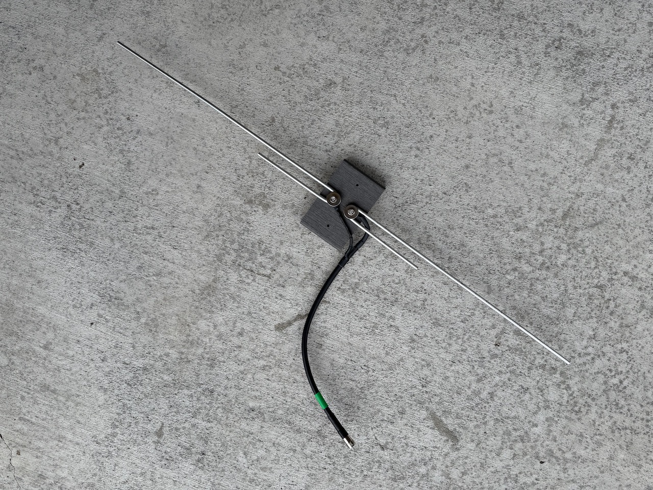
Doing a web search, as one does (albeit with DuckDuckGo, not the big G site anymore), I ended-up getting a lot of video results. (Ugh. I hate YouTube and YouTube videos with a passion.) But nevertheless, the still image for one particular video intrigued me. The video in question was from Dariusz Frankiewicz, SQ8LAB. He used two J-shaped elements to create an interesting take on a fan dipole. I decided I’d just use his element configuration and lengths as-is, but do something a little different for the mount.
Before I got stuck-in, I decided to see if the lengths Dariusz quoted were consistent with what others had mentioned (they were); the short UHF element was spec’ed at 16cm, and the longer VHF element was spec’ed at 47cm. So, on with it.
Like Dariusz, I used aluminum rod for the elements, in my case, 1/4″ (~6mm) diameter material, which was readily available at the local big-box home center store in 3′ (~1m) lengths. While at the home center, I chose some stainless steel hardware (machine screws, fender washers, nuts, split lock nuts, wood screws for mounting) for the project.
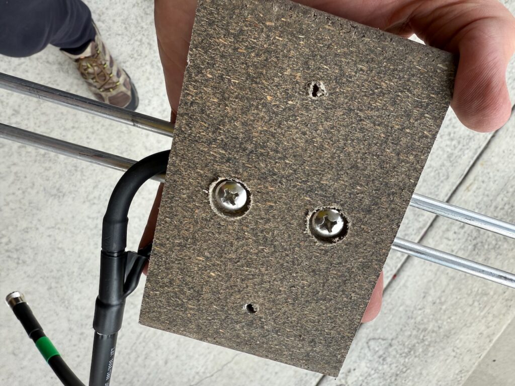
I also walked around, trying to spy anything suitable for a non-conductive, weatherproof base. I happened to stroll through the lumber section, and stumbled across free samples of Trex, a wood/plastic composite decking material common here in the USA. Free is a great price, and the block was perfect for my needs. Score!
Next, I used Adobe Illustrator to create a perfectly to-scale bending guide for the rod to ensure that the UHF element was precisely the correct length. (I would cut the rod to length for the VHF element.) That ended-up working nicely as I bent the rod by hand, using the shelf of a metal storage rack (a knock-off of the popular Elfa shelving system) as a bending form; it worked great, and the rods were perfectly formed. Next, I measured the VHF element, and cut the excess.
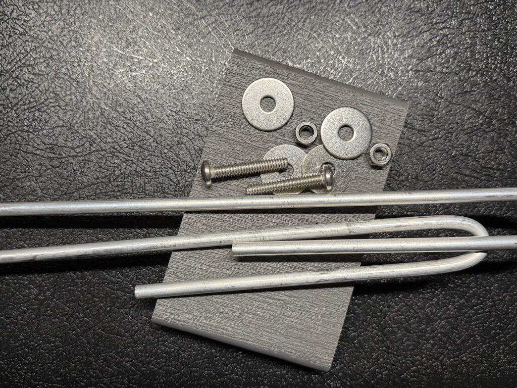
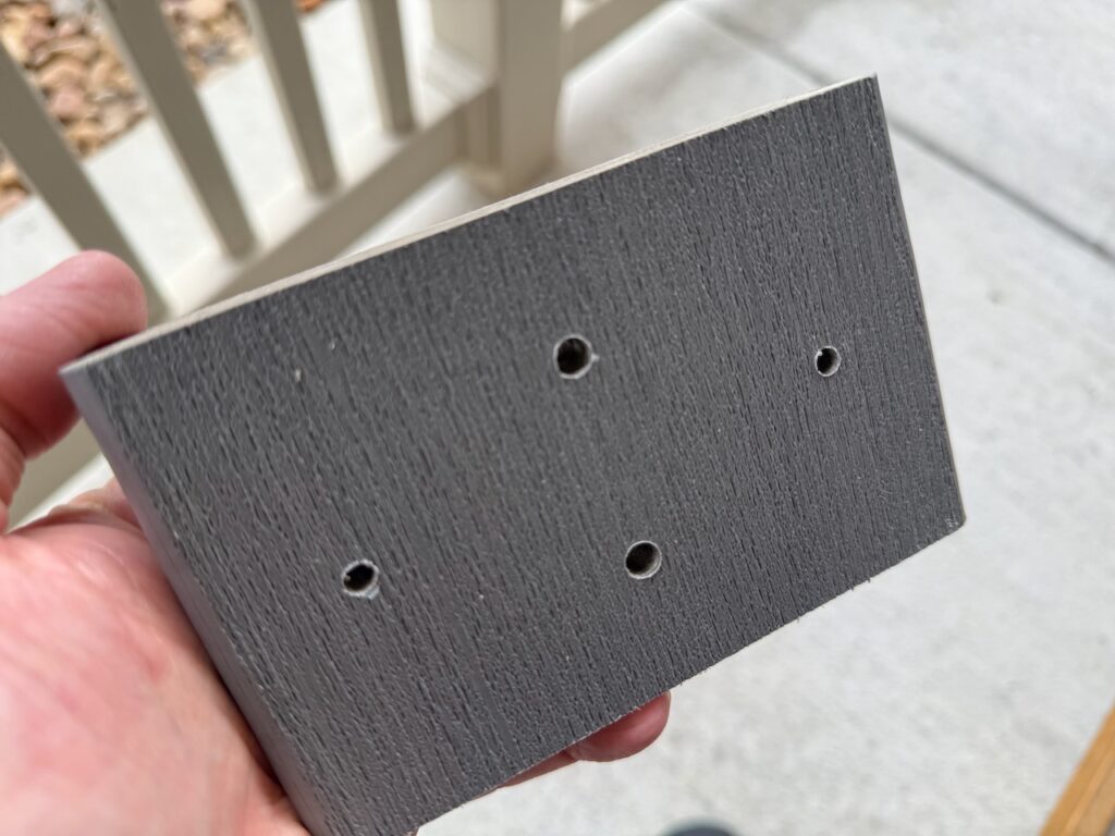
Next, I measured and marked where I wanted to drill holes through the Trex block for the hardware both to affix the rods, and to mount the result to the wooden fence that would serve as its mast. After drilling, I used a boring bit to create a countersink on the back side of the block where the screw heads could recess.
To feed the antenna, I decided to use an ABR Industries 2213A-SO-RT-1.5 from Ham Radio Outlet. Unfortunately, this ended-up being the most expensive component of the project at roughly US$35. (Ouch.) But I had very little interest in terminating and weatherproofing a short length of coax myself, and I needed a new RG8X feed line for this antenna anyway, so I’d be at HRO getting that.
Assembling the antenna was simple. Feed the screw through the back, then the ring terminal from the ABR coax jumper, then the element, then a fender washer, then a split lock nut, and finally the nut itself. Then, tighten fully.
I made sure that the ring terminals were positioned such that the raw end of the joint with the ring terminal was upside down, to prevent water from potentially seeping directly into the coax over time; the terminations themselves are very nicely dressed and weatherproofed, but I still felt it was a good idea not to invite trouble.
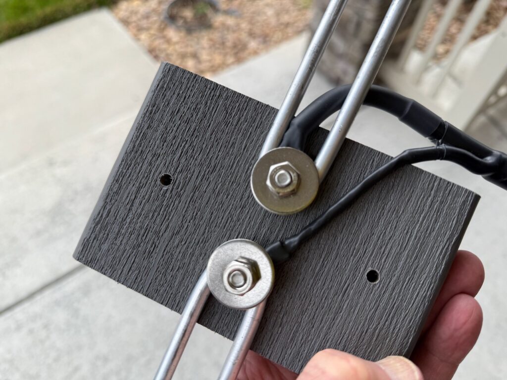
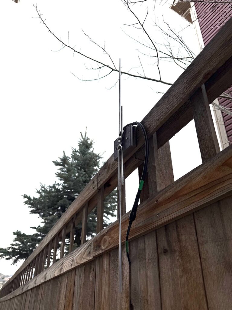
Soon enough, the antenna was finished. All that was left was to run a new feed line from shack, mount the base to the top of a wooden fence as planned, connect and weatherproof the connection between the coax feed to the coax jumper on the antenna with some silicone tape, and call the project done. It is worth noting that the “positive” element (connected to the center of the coax) points upward, while the “negative” (jacket) points downward.
With some rudimentary testing, it appears that it performs rather nicely. SWR mid-band on both 2m and 70cm is a perfect 1:1. And quite frankly, I’m just not used to the popular Front Range Colorado repeaters being so… quiet (as in, no noise).
At home, I plan to use the antenna with my TIDRadio TD-H3 handheld, as well as my Icom IC-7000. The antenna is not in what I’d consider to be an “optimal” placement, but it’s what I can easily manage, and for my uses, it needn’t be any higher up. Should that need present itself in the future, I have some options for that, but for now? It’s a very nice improvement over my previous makeshift solution, and one that is demonstrably far more optimal.
Not bad for a small investment, and about 90 minutes of effort. Here’s the end result, in-place.